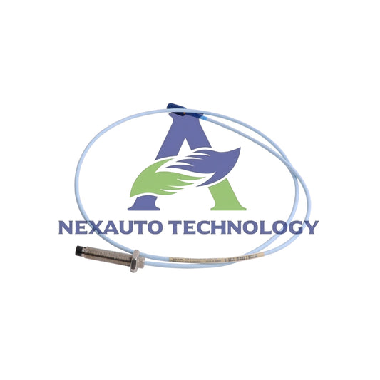
What Every Engineer Should Know About Bently Nevada Sensor Calibration in PLC & DCS Systems
Why Calibration Matters for Control Systems
Accurate sensor readings are critical for safe and efficient industrial operation. A 3300-series Bently Nevada proximity probe, for example, provides voltage output between 0–10 VDC corresponding to a 0–50 mils gap. Improperly calibrated sensors can trigger false trips or fail to detect real machinery faults, leading to unplanned downtime, safety incidents, or equipment damage. Field data shows that over 15% of false trips in turbomachinery were traced to unverified sensor gaps. Regular calibration ensures PLC and DCS logic reacts to reliable input signals, minimizing operational risk.

Bently Nevada Sensors: Types and Factory Calibration
Bently Nevada supplies proximity probes, accelerometers, and vibration transmitters designed for high-reliability industrial monitoring. Most 3300-series proximity transducers ship factory calibrated to standard test targets (steel disk, 440C or aluminum alloy). For example:
- Proximity probe 3300 XL, 8 mm diameter: factory gap calibrated at 25 mils ± 2 mils
- 3300 XL Accelerometer: factory sensitivity set at 100 mV/g ± 5% across 0–500 Hz
- 990-05-70 Vibration Transmitters: calibrated output of 4–20 mA for 0–50 mils displacement
Field engineers typically verify calibration points rather than performing complete re-calibration, saving time and reducing risk of error.
Field Calibration Methods: Static and Dynamic Checks
Two primary methods exist for on-site verification:
- Static Checks: Measure gap vs. voltage at multiple reference points (e.g., 10, 20, 30, 50 mils). Verify linearity and zero offset. Acceptable error: ±1 mil for critical rotors.
- Dynamic Checks: Use calibrated shakers or machinery operation to confirm frequency response and phase. Recommended frequency range for typical machinery: 0–1000 Hz. Tolerable gain deviation: ±5%.
Both methods complement each other and ensure measurement integrity under real operational conditions.
Standards That Govern Vibration and Sensor Calibration
International standards provide guidance for repeatable calibration:
- ISO 2954: Defines accelerometer calibration procedures and sensitivity limits.
- API 670: Specifies minimum requirements for machinery protection systems, including proximity probe and transmitter calibration.
- IEC 61508: Governs functional safety for sensor output reliability in safety-related control systems.
Integrating Calibrated Signals into PLC and DCS
Proper signal integration requires attention to scaling, offset, and wiring. Typical guidance:
- Verify channel zero: 0 VDC for 0 mil gap
- Verify channel span: 10 VDC for 50 mil gap
- Confirm wiring continuity and shield integrity: resistance < 1 Ohm, insulation > 100 MΩ
Technicians should always follow module manuals for zero and span procedures. Automated alarms in PLC/DCS should match verified sensor ranges for reliable fault detection.
Frequency of Checks and Calibration Records
Calibration schedule depends on asset criticality and operating hours:
- Critical turbines: every 3–6 months or 500–1000 operating hours
- Secondary pumps: annually or 2000 operating hours
- Document each calibration: include date, technician, measured voltages, and gap values. Well-maintained records facilitate troubleshooting and audit compliance.
Common Field Pitfalls and How to Avoid Them
- Cabling errors may alter phase and amplitude readings. Verify cable lengths and shield continuity.
- Different target materials can affect probe sensitivity. Confirm target metal matches factory calibration target.
- Temperature variations: ensure measurements account for thermal expansion (typical 0.2% per 25°C change).
Tools and Practical Techniques for On-Site Calibration
Recommended tools include:
- Calibrated shakers with ±1% amplitude tolerance
- Static calibration fixtures
- Precision gauges for gap verification at 10, 20, 50 mils
- Proximitor driver voltage check: nominal 12–14 VDC
- Channel scaling verification in PLC/DCS after adjustments
Author’s Insight: A Reliability-First Calibration Strategy
Adopt a risk-based calibration schedule:
- Start with static checks for all assets
- Perform dynamic calibration for rotors exceeding 2000 RPM or critical bearings
- Align alarm thresholds in PLCs with verified sensor ranges
- Review historical vibration trends to identify sensors that drift over time
Application Cases / Solution Scenarios
- Turbomachinery Monitoring: Install 3300 proximity probes, verify gaps during commissioning, and record all static measurements.
- Boiler Feed Pumps: Conduct dynamic shaker tests after coupling replacements to confirm vibration signal integrity.
- Retrofit Projects: Remap DCS scaling when replacing proximity transmitters, confirming both zero and span across operational range.

Practical Checklist for Engineers
- Confirm factory calibration and target material used
- Inspect wiring, connectors, and shield continuity
- Run static gap checks at defined points (10, 20, 50 mils)
- Perform dynamic verification for critical assets
- Update PLC/DCS scaling, log all results, and attach calibration certificates
Implementing these practices ensures reliable data input for PLCs and DCS, reduces false alarms, improves machinery protection, and maximizes plant uptime.
Check below popular items for more information in Nex-Auto Technology.

