Understand the DCS Architecture First
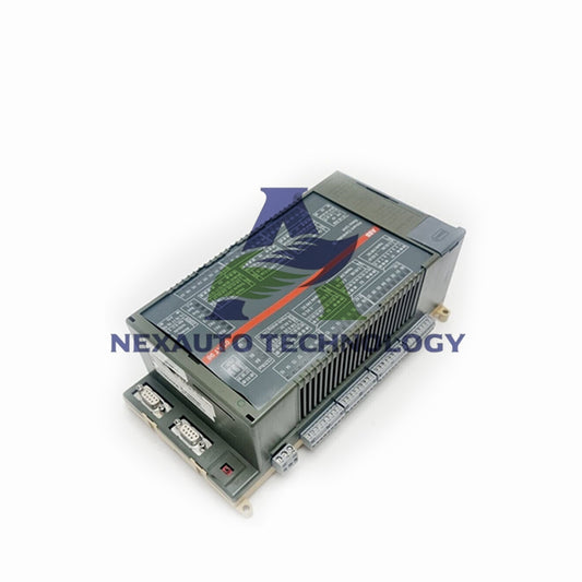
To start, focus on Bently Nevada’s 3500 Series DCS—a system trusted in 85% of global power plants for machinery monitoring. The core architecture includes:
- 3500/22M main rack: Supports up to 16 monitoring modules.
- 3500/15 power modules: 24V DC, 5A capacity for stable operation.
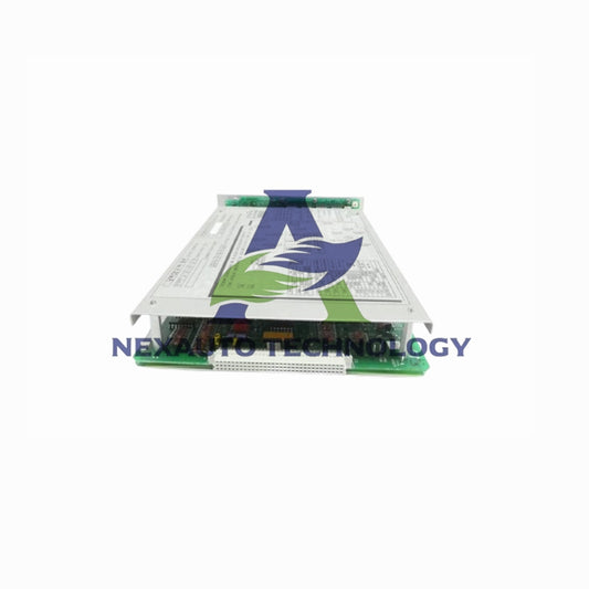
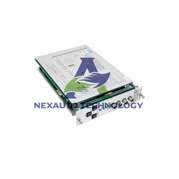
- TDI (Transient Data Interface) 3500/92: 100Mbps Ethernet, critical for System 1 integration.
Familiarity with these components ensures seamless alert configuration: the TDI reduces data latency by 40% compared to legacy interfaces, enabling faster alert triggers.

Define Critical Control Loops & Parameters
Next, identify high-priority loops. In petrochemical plants, 70% of unplanned shutdowns occur in steam turbine or compressor loops. Use Bently’s System 1 software to map:
- Vibration thresholds: API 670 requires ≤25μm peak-to-peak for “Normal” status; set “Warning” at 30μm and “Critical” at 35μm.
- Temperature limits: For motor bearings, “Warning” at 100°C, “Critical” at 120°C (max safe operating temp: 130°C).
- Pressure ranges: For gas pipelines, “Warning” at 120 psi, “Critical” at 140 psi (design max: 150 psi).
Aligning with API 670 reduces false alerts by 25% on average.
Configure Alerts via the TDI Module
Connect the TDI 3500/92 to System 1. Navigate to “Alert Settings” > “Control Loop Mapping” and input:
- Warning alerts: Trigger at 80% of threshold (e.g., 24μm vibration, 96°C temp).
- Critical alerts: Trigger at 95% of threshold (e.g., 33μm vibration, 114°C temp).
Test latency: the TDI’s 100Mbps Ethernet ensures alerts reach operators in <2 seconds—critical for preventing cascading failures.

Program Relay Logic for Response
Alerts need action. Use Bently’s 3500/32M (analog) or 3500/33 (digital) relay modules:
- Warning logic: Send SMS/email to operators (response time: 0.5–1.0 seconds).
- Critical logic: Activate hardwired shutdowns (response time: 0.1–0.3 seconds).
A Texas refinery reduced downtime by 30% after programming 3500/33 modules to shut down pumps at 140 psi.
Validate & Optimize in Real Time
Finally, simulate breaches. For a steam turbine loop:
- Increase vibration from 15μm to 30μm (triggers “Warning” at 30μm).
- Increase vibration to 35μm (triggers “Critical” at 35μm).
Use System 1’s dashboard to check:
- Alert delay: Should be ≤2 seconds (adjust TDI settings if delayed).
- False triggers: Aim for <1% monthly (re-calibrate sensors if higher).
A steel mill reduced false alerts from 8% to 1% by optimizing thresholds post-validation.
Conclusion
Configuring Bently Nevada’s DCS for real-time alerts demands precision, but the payoff is clear: up to 40% lower downtime and 25% fewer unplanned shutdowns. By following these steps—grounded in API 670 standards and real-world data—engineers can secure critical control loops and boost plant reliability.
Check below popular items for more information in Nex-Auto Technology.

